Load-in day at a 1,200-seat multi-purpose hall. The fly tower tops out at 12 m, the lighting design calls for a 9.5 m batten with 14 independently motorized points, and the polished concrete floor must host a corporate dinner the next evening. There is no time to build a permanent grid; there is one weekend to turn the room into a theatre. This is the scenario where mobile zero-fleet stage winches are planned from the first site survey, not introduced as a fallback.
RenteZhihe (JiangSu) Equipment Technology Co., Ltd. builds the winches, but the venue team and the installer decide whether the layout succeeds. Load paths, floor preparation, power drops, and control architecture are the decisions that separate a clean load-in from a stop-work incident, and they are made before the first unit leaves its flight case.
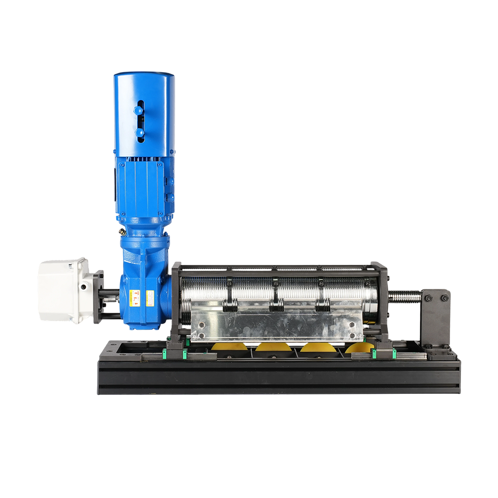
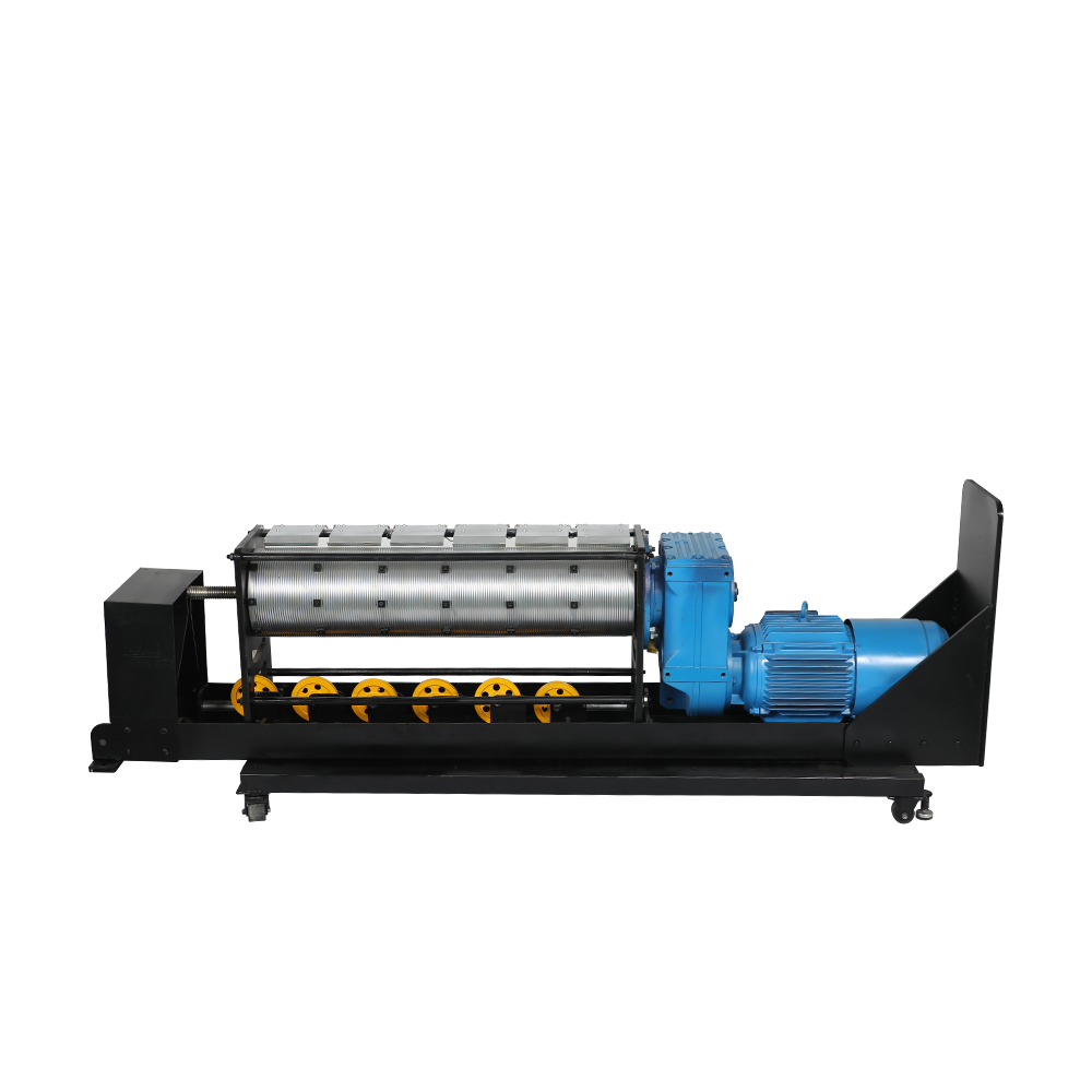
A mobile zero-fleet stage winch is a portable hoisting unit whose single-layer grooved drum holds the wire rope at a 0 degree fleet angle, so the load point stays horizontally fixed across the full travel distance.
A standard drum winch with a 1.5 degree fleet angle pulls the load roughly 400 mm sideways over a 20 m lift. Fixed structures tolerate that drift; portable units rigged to batten trim marks do not. The zero-fleet drum removes the geometry problem mechanically instead of asking software to compensate for it.
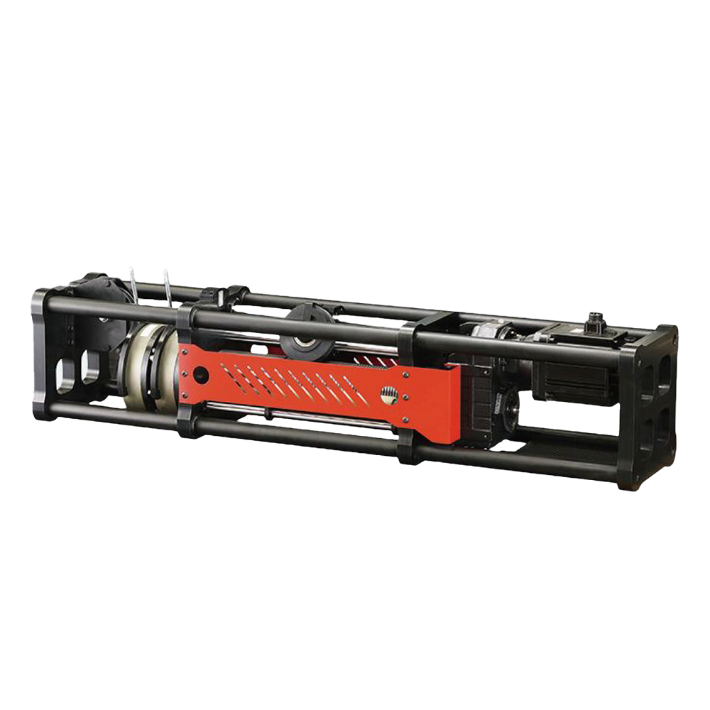 Mobile Zero-Fleet Stage WinchRedefining portable stage machinery, the Mobile Self-Tailing Winch features a sleek, compact design tailored for solo lifting points on the go. Driven by a servo syste...View Product →
The load path is the continuous chain from the suspended batten through the wire rope, drum, winch frame, base plate, and dunnage into the floor slab, and every layout position must pass that chain test. The most common error is placing winches where power outlets already exist and bending the rigging plan around the architecture. Fix the batten positions first, work backwards to the winch, then bring power and data to the unit.
If the venue team needs a second opinion on spacing, request a layout review before the contract locks the load positions onto the drawings.
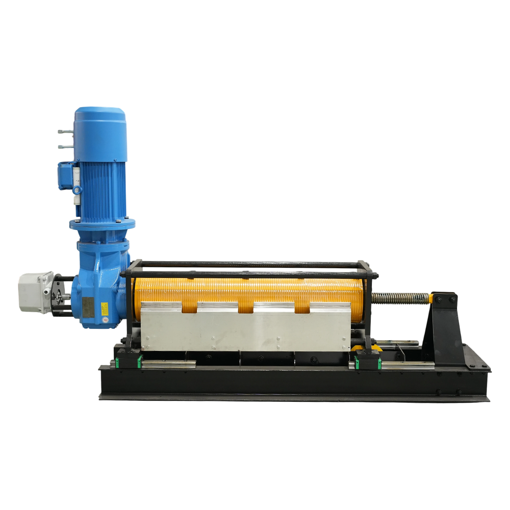
Where wing space is tight, an inline zero-fleet winch keeps the rope axis aligned with the haul direction, so the unit sits in a corridor instead of reshaping the rigging plot. Both standard and compact variants need the same minimum deflection radius above the drum, so confirm headroom before committing to a position.
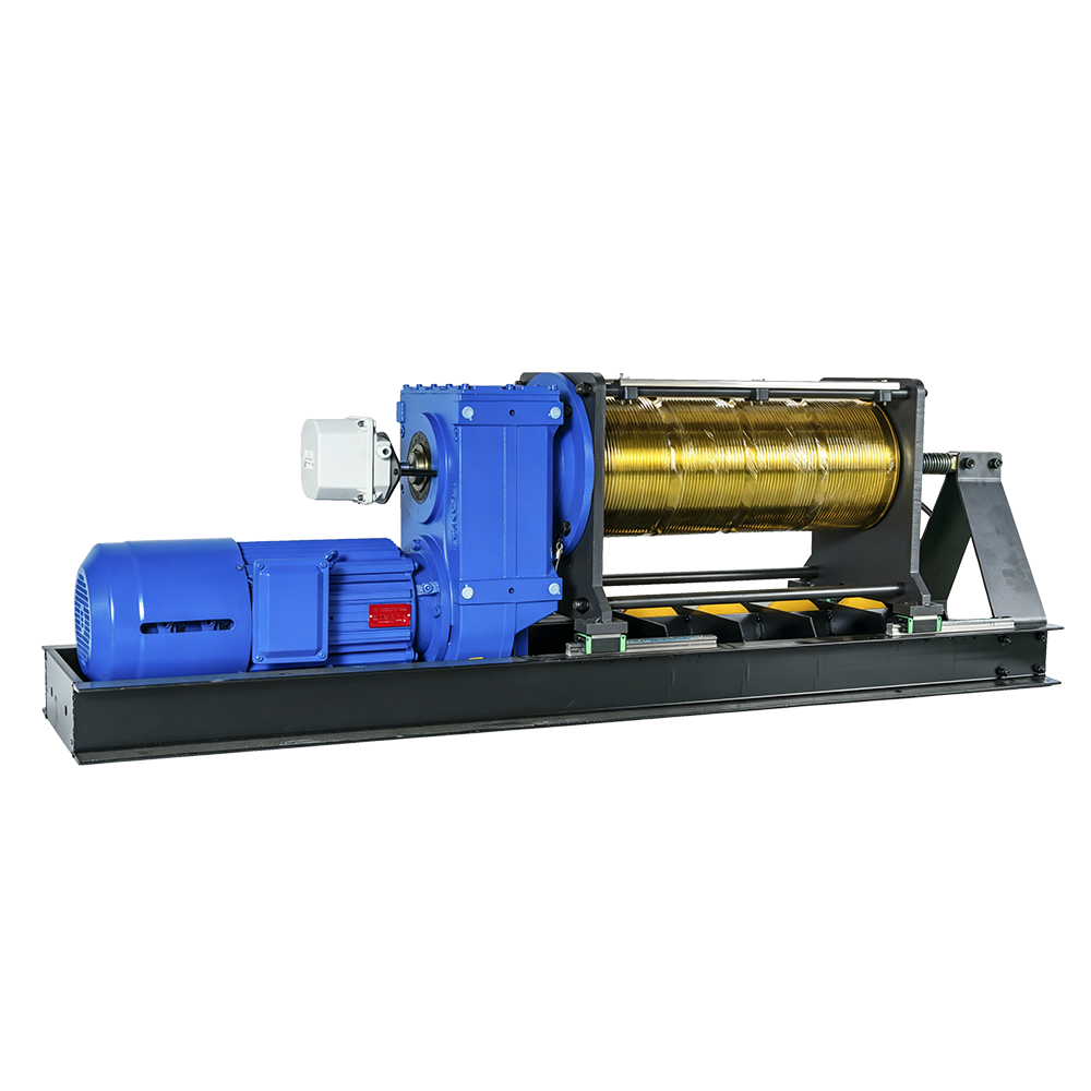 In-Line Zero-Fleet Stage WinchThe “Single” series represents the pinnacle of intelligent winch design, featuring a unique dual-encoder system paired with a dual-brake motor for pinpoint accuracy. D...View Product →
| Check item | Target value | Why it matters |
| Slab load at each dunnage foot | 5 kN or below after spreading | Prevents surface micro-cracking |
| Distance from unprotected deck edge | 600 mm or more | Preserves edge shear capacity |
| Rope deflection radius | 300 mm minimum | Prevents wire fatigue and abrasion |
| Lateral anchor capacity | 1.5 times rated pull | Covers hard stops and dynamic sway |
The floor slab is the foundation of a temporary rigging system; if it cannot carry the projected point loads at the marked positions, the plan fails before installation. A 900 kg winch pulling a 2,500 kg batten can put nearly 1.5 tonnes on each dunnage foot during worst-case braking. A reinforced concrete slab rated at 5 kN per square centimetre absorbs that easily; a 20 mm screed layer over insulation does not.
Shim every winch base to plus or minus 2 mm of level. Anchor bolts provide lateral stability; where the venue forbids drilling, a ballasted base of concrete blocks or steel plates must match the same anchor capacity calculated for the floor.
Each winch needs a 400 V three-phase circuit at 32 A with a protective earth. Data runs travel in separate trays, and the emergency-stop loop follows its own route. Mark every drop during the survey so installation crews are not cutting floor covers on load-in day.
A temporary rigging network must carry the same safety architecture as a permanent installation: a closed-loop emergency-stop chain, certified limit switches, and real-time position feedback. Power, data, and the safety loop are three separate paths and never share a conduit bundle.
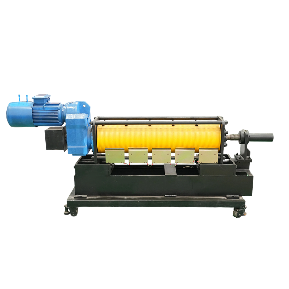
Multi-axis synchronization runs over EtherCAT or an equivalent industrial protocol because the round-trip latency of that link decides whether 14 winches keep one batten level. The emergency-stop chain uses monitored continuity; an open loop freezes all axes within 200 ms. For cues above normal speed or sub-millimetre positioning, the servo-driven zero-fleet winch is the unit specified.
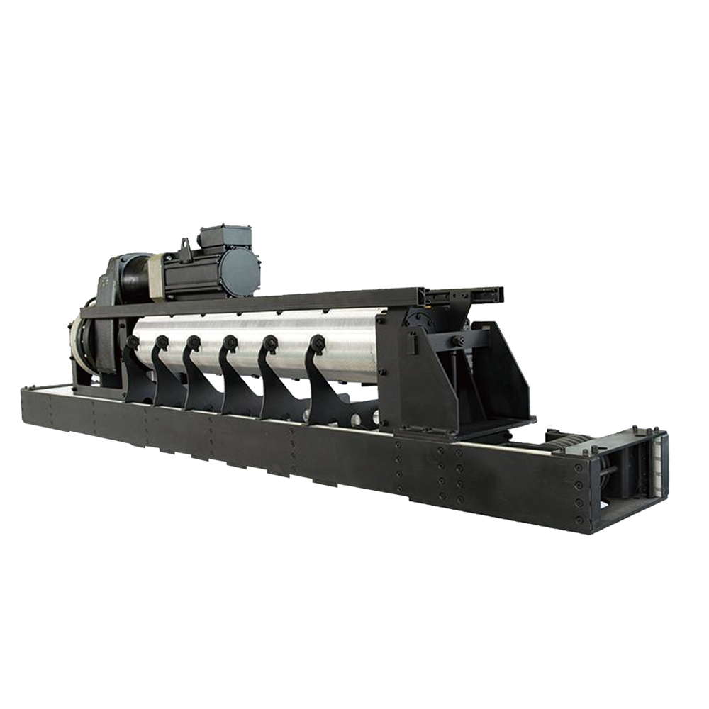 Servo-Driven Zero-Fleet Stage WinchFor applications demanding the ultimate in speed and precision, the Servo Series Stage Winch is the answer. Driven by an advanced electric servomotor, it boasts an ult...View Product →
The field-proven sequence is survey, position, rig, terminate, test, proof-load, and program; skipping one step to save an hour adds a day of rework.
A dedicated stage machinery installation and commissioning service can run the complete sequence for an eight-winch layout in two and a half days on a prepared floor.
Mobile zero-fleet winches sit under the same machinery safety framework as fixed winches: wheels change the installation, not the safety classification. Most venue jurisdictions accept documented compliance with EN 17206 acceptance testing and the applicable machinery directive, with control risk assessments aligned to SIL logic. Ask the supplier for the Declaration of Conformity, load test certificate, inspection log templates, and operator training records as part of the delivery package.
No. Level the base to plus or minus 2 mm before rigging. On concrete use steel shims; on event decks build a plywood and dunnage platform; on outdoor ground use spreader plates and verify the bearing capacity.
Each unit typically needs a 400 V three-phase supply at 32 A with a protective earth. Arrange power drops before load-in; cables routed through doorways create trip and damage risks that safety audits will flag.
Yes. The winches accept EtherCAT, PROFINET, and digital I/O interfaces. The connection is commissioned together with the emergency-stop chain and verified during the proof-load sequence.
An eight-winch layout on a prepared floor with power and level positions is installed, tested, and programmed in two and a half days. Add a full day when site preparation is not complete.
We specialize in delivering advanced stage machinery, rigging systems and intelligent control solutions for performance spaces worldwide.

No. 111 Runfeng Road, Hailing District, Taizhou City, Jiangsu Province, China

rtstage@163.com

+86-139 1771 1698

+86-139 1771 1698
rtstage@163.com
 中文简体
 English
 русский
 Français
 Español
 عربى